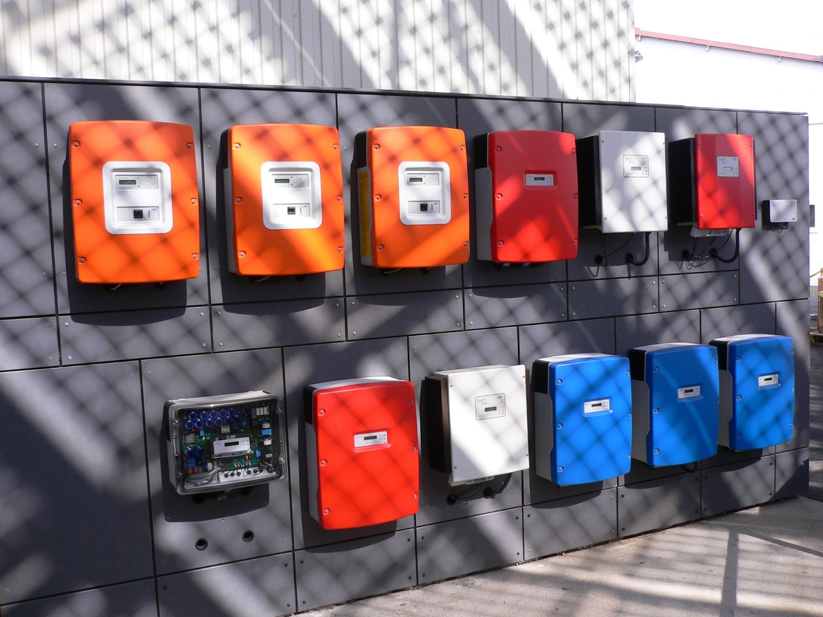
Comparison of string inverters and microinverters

Solar inverters provide electricity to your home by converting the direct current (DC) that is generated by solar panels into alternate current (AC). Microinverters as well as string inverters perform the same function as a solar homeowner but go about it differently. With the continuous evolution of inverter technology, homeowners can harness the maximum amount of energy from their solar PV systems. We explain string innovations in this article to help you decide the best approach to integrate them into your solar energy system.


How do string inverters work?

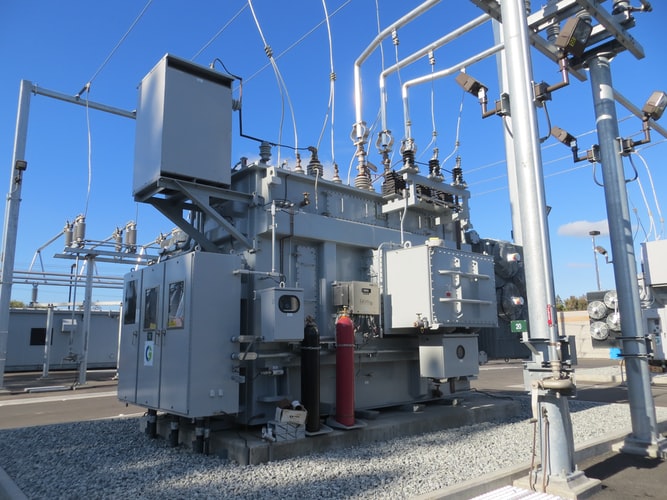
String inverters (also known as “central inverters”) are standalone equipment located near your main service panel and electricity meter. The size of an individual solar installation typically dictates the number of inverters, which may be one or two. The solar panels in a “series string” usually come in sets of six to twelve. SMA is a manufacturer of string inverters. The company behind the solar panels is SMA.

The advantages of string inverters

An inverter for AC power conversion is all you need to set up a solar string since only one is needed. When something goes wrong with a solar system, the inverter is likely to fail – making troubleshooting relatively easy. Many microinverters are more expensive than string inverters since they require more labor hours to install. Solar panels are not connected. String inverters are less likely to be improperly connected.

String inverters have some disadvantages

Solar energy systems are not cheap to add rapid shutdown capabilities. Depending on what regulations your area adheres to, you will either need additional labor or wiring to ensure your system meets the requirements. String inverters require that solar panels are wired in series and if one panel fails, the whole string is affected. Microinverters have a warranty of between 8 and 12 years, whereas string inverters have a warranty of 25 years.

How does a microinverter work?

A microinverter is the same as a string inverter but is installed beneath each solar panel. Solar panels and micro inverters can each contribute as much power as they can. Although electricity is not converted into AC behind each panel, the work is still done at the string in the other part of the circuit with power optimizers. Microinverters from Enphase have been on the market since 2009 and have become an integral part of their thriving business.

Advantages of microinverters

To prevent high voltage electric shocks while first responders or firefighters are on roofs or servicing power lines, new electrical codes require rapid shutdown of solar systems. Embedded in each microinverter module is the capability of the rapid shutdown. When there are multiple angles on a solar system, such as some panels facing south, some facing east, and some facing west, microinverters are the way to go. You should use micro inverters if you have shade issues from trees or a large chimney.


Deficiencies of microinverters

Microinverters are primarily disadvantageous due to their high cost. Typical string inverters on a 5kW residential solar installation cost $1,000 or more. It’s not as easy as putting a new string on the side of your house if one of your solar panels fails. Shake roofing materials may not be a good choice if you live in a storm-prone area and have an old wooden structure.

How do Microinverters and String Inverters compare?

SolarReviews remains skeptical of claims that microinverter failure rates are very low. Manufacturers advertise the ability to monitor each panel as a benefit (and it is), but do not include the monitoring that would allow the customer to do so. The failure of only one or two inverters can be difficult to diagnose using only system-wide monitoring data. Inverters are generally easy to notice when they fail because they stop the whole system.


If you’re looking for the best place to get your inverters, you’re in the right place! EP-Power aims to give you a total commitment to ensure the best quality and provide first-class products and services.

For inquiries, you may send us an email at: sales@edac.com.sg or give us a call at +6564547877. 


Electric Vehicle Charging Framework in Singapore

Introduction

Electric cars first appeared in 1820, however, the limitations of power didn’t bring them to the limelight until the 20th century. Governments of several countries have shown great interest in adopting electric vehicles. As early as mid-2017, BlueSG Pte Ltd, a Bolloré Group subsidiary, will offer electric car-sharing services in Singapore. Additionally, electric vehicles reduce noise pollution, have low maintenance costs for consumers, make good use of vehicle space, and are easy to drive.

Despite the above developments, several factors still obscure the prospects of EV. A few of these factors are the battery life, charging time, availability of charging stations, the cost for charging, and safety. EVs might be required to be charged in scenarios where they still have reasonable charge and these scenarios could put the EV driver in a dilemma as the margin is limited compared to vehicles powered by internal combustion engines (ICEs)

Singapore is unique because it covers a total area of 719.1 km2 and averages about 50 km per day in car travel. EV charging stations in most countries are concentrated around specific neighborhoods and hence the cost of charging (uniform charging or dynamic charging) could significantly affect the EV user behavior. Electricity companies may charge different rates during non-peak times as well as during peak hours. Singapore does not have dedicated charging points since most people live in public flats.

EV Battery and Charger

Table 1 compares the battery power capacity, range, cost per km, and charging time for typical EVs currently available in the market for typical EV vehicles. Lithium-ion batteries require the least maintenance, are less susceptible to memory effect, and require no scheduled cycling. For subcompact EVs, the batteries have an energy capacity of 12 – 18 kWh, for mid-sized family sedans, 22 – 50 kWh, and for luxury models, such as those from Tesla, 60 – 85 kWh. The charging rate of the battery depends on the type of charger used and the initial charge in the battery.

Most EVs or EV users have smartphones that can be enabled to communicate with charging networks. The EVs could also be equipped with built-in communication modules. The charging network would be responsible for sharing the parameters in Table 3 while maintaining privacy. This information may also be used by EV manufacturers to examine their batteries and performance. Charging stations can analyze the charging patterns of EV users in order to adjust their pricing and business models.

Charging Station Selection Criteria

Our method of calculating travel times based on the Google Maps API allows us to rank the five easiest charging stations according to their travel times. Pricing factors affect the charging station criteria. Table 3 lists the parameters that we used when simulating an EV charging network with JAVA programming. We used the standard Singaporean exchange rate, which is S$3.99 to S$5.99. Google Maps was also used to calculate distance and estimate the charging station’s location.

Simulation

With the parameters listed in Table 3, we used JAVA programming to simulate the EVs and the 30 charging stations. Google Maps was used to estimate the distance between the EV and the charging stations as well as the time it would take to reach the charging station under realistic traffic conditions. We randomly assigned p! Singapore taxi rates with a flag down fee of S$3.40 and a per-kilometer fee of S$0.44 range from 5.99 to 14.99 Singapore dollars. Figure 1 illustrates EV charging stations in Singapore.

If you’re looking for the best place to get your power supplies, you’re in the right place! EP-Power together with Magna-Power aims to give you a total commitment to ensure the best quality and provide first-class products and services.

For inquiries, you may send us an email at: sales@edac.com.sg or give us a call at +6564547877. 


What is Deep Discharge? How To Build A Simple Battery Protection Circuit

Batteries you use in a variety of projects, from uninterruptible power supplies to remote-controlled cars, may be damaged by deep discharging. Learn about deep discharging and how to protect your batteries. Here you will find helpful terms and a simple circuit that can protect your battery-powered projects from malfunctioning.

What is Deep Discharging?

A deep discharge occurs when the capacity of a battery has been exhausted. Battery cells have a set voltage at which they cease to function. This voltage is called the cut-off point. Exhausting deep causes 1.5 to 2 times as much electric discharge as the battery can support. As a result of over-discharging, the battery will have increased internal resistance, making charging difficult. The price tag on these batteries is high.

Depth of Discharge

According to the Depth of Discharge chart, the battery has used a percentage of its capacity as compared to its total capacity. If the batteries’ full capacity is 15kWh and you discharge 12kWh, that’s 96%. As a result, a deep discharge is something you should avoid. A deep cycle battery is a battery that is designed for deep discharge regularly. Power storage, UPS, traffic signals, and remote applications use these batteries.

Deep Discharge Protection Circuits

Identification of the battery’s cut-off voltage is necessary for deep discharge protection. A Zener diode in reverse bias condition will act as an open circuit when its cathode voltage falls below the breakdown voltage. It starts conduction when the cathode voltage is above its breakdown voltage. A switch disconnects the load from the battery, thus disconnecting the battery from the device. When the batteries reach the cut-off voltage level, we need to design a circuit to turn on a switch.

Protection Circuit for 12V Batteries

We will build a protection circuit to protect the load and battery from over-discharging, we will build a protection circuit. To adjust the resistance to achieve the desired range of operation, we’ll use a similar circuit but change the resistance. The diode is no longer conduction and there will be no base voltage, which effectively disconnects the battery from the load when the voltage is below 8V. We hope to use this circuit to protect the battery and the load from overcharging.

ICs Used for Over-Discharge Protection

Cs make our work easier when we are dealing with a complex circuit and have to regulate the power for the load. It is possible to replace several circuits with one integrated circuit. Integral circuits are capable of simultaneously monitoring and controlling power flow. Two integrated circuits can handle this application.

The LTC2960

A high voltage multi-cell battery monitor, the LTC2960 IC provides two input voltages. If the battery voltage is low, the RST pin in the IC signals a low voltage by going high. A user can provide the IC with either inverting or non-inverting inputs. Portable battery-powered equipment, batteries, and other systems commonly use this IC.

The LT1495

LT1495s are low-power op-amps that are capable of delivering very low supply currents. The supply can be fitted to 3V, 5V, or +- 15V. With a voltage range of 2.2V-36V, this device makes it possible to regulate a wide range of voltages. This IC offers several advantages over other protection circuits, including the fact that the circuit made by the IC uses less than 4.5miliamps of current. The device also protects batteries up to 18V.

How to Charge an Over-Discharged Battery

When a battery is overcharged, its internal resistance increases. Battery capacity can be lost twice as a result of this, so the battery has a hard time being recharged. When the voltage drops below 3.0V, severe damage occurs. Check the battery periodically for heat buildup and do not leave it unattended. In this situation, charges can be reduced. During puffing or overheating, it is impossible to restore the battery. Charges from batteries follow a similar pattern.

If you’re looking for the best place to get your power supplies, you’re in the right place! EP-Power aims to give you a total commitment to ensure the best quality and provide first-class products and services.

For inquiries, you may send us an email at: sales@edac.com.sg or give us a call at +6564547877. 

Voltage sags are the most common cause of poor power quality. They are also the most costly. The more complex a plant is, the more voltage sags it is susceptible to, such as in-process controllers, PLCs, variable speed drives, and robots. A sag in voltage can cause relays and contactors in motor starters to fail, resulting in a shutdown.

Voltage Sags: What causes them?

Voltage sags are the most common cause of poor power quality. They are also the most costly. The more complex a plant is, the more voltage sags it is susceptible to, such as in-process controllers, PLCs, variable speed drives, and robots. A sag in voltage can cause relays and contactors in motor starters to fail, resulting in a shutdown.

Power quality is mainly affected by voltage sags. In addition to being the most expensive, they also have the longest lead times.

Complex industrial equipment, such as process controllers, PLCs, adjustable speed drives, and robots, is more sensitive to voltage sags as their complexity increases. As a result of voltage sags, motor starter relays and contactors break down, causing downtime.

What are voltage sags?

According to IEEE, voltage sag refers to a short-term reduction in voltage. At 60 Hz, the magnitude of the voltage reduction is between 10% and 90% of the normal root mean square voltage (RMS). By definition, a voltage sag event lasts less than 1 minute and more than 8 milliseconds, or a half cycle of 60-Hz electrical power. Undervoltage, transients, voltage unbalance among phases, voltage fluctuations, and electrical noise are also power quality issues affecting voltage amplitude and duration.

What causes voltage sags?

In both directions of an electric meter, power quality issues exist. It is typically the local utility that is blamed for voltage sags. The equipment within a plant is often to blame for voltage sag events. Switching operations are the most common human-created events. Human-created events, like switching operations, also constitute the majority of natural events. Even if the problem is caused by sags in power meters or other power quality issues, it’s difficult to determine the source of the issue.

Lightning
Wind
Trees falling onto power lines
Construction workers digging into buried cables
Squirrels and rodents
Equipment failures
Traffic accidents.

During voltage sag, there can be a difference in individual phase voltages and an accompanying phase-angle shift. The most common cause of sags is a single-line-to-ground fault (SLGF). Double and three-phase symmetrical faults are rare, occurring less than 20% of the time. Users beyond a 100-mile radius of the causing event can be affected by voltage sag on the grid. In some cases, a large motor can also cause voltage sags within the plant.

Detecting voltage sags

Monitoring power quality can detect voltage fluctuations, surges, interruptions, and other issues related to power quality. Power is measured as it enters a facility and compared with accepted standards. Systems that provide web-enabled power monitoring provide information on total harmonic distortion (THD), voltage, power factor, current demand, voltage unbalance, voltage sag, voltage swell, and alarms for multiple locations. Using one browser, a company in central Tennessee can monitor its facilities in Mexico, Canada, and across the country.

Simulation devices

Typically, the utility is responsible for sag, Undervoltage, and interruption events that occur outside the plant. Contacting the utility should be made when power quality problems occur, but when they occur within the plant, plant personnel should determine the cause. This problem may be resolved by providing more power, lowering the voltage drop, and using a soft-starting method. Several industrial devices can be easily tested for sensitivity using the sag generation apparatus.

Voltage sag reduction

Uninterruptible power supplies (UPS), constant voltage transformers (CVT), and solid-state sag correction devices are common power line conditioning technologies. The location of a machine affects its voltage sag sensitivity. Increasing wire size can reduce voltage drop when the wiring is to blame. The plant service entrance can often be used as an entry point for sag correction devices, such as on the control panel, at the machine level, or at the bus level. During voltage drops, momentary power blackouts, and extended power outages, UPS devices provide protection.

Power quality: A relationship-based challenge

Power quality and the ability to reduce the need for reliability and dependability must be understood in order to solve problems. Assuring PQ’s impact on operating facilities, and minimizing the costs of solving problems, requires an understanding of its relationships. Power quality problems are typically caused by the addition of new, more sensitive devices to an existing plant, not by a change in the power coming from the utility. A manufacturer knows the relationship between raw materials and the finished product. Why would a manufacturer losing $100,000 per year to scrap, misdirected labor, and lost production not spend half as much to stop these losses?

If you’re looking for the best place to get your power supplies, you’re in the right place! EP-Power together with TREK AND MONROEaims to give you a total commitment to ensure the best quality and provide first-class products and services.

For inquiries, you may send us an email at: sales@edac.com.sg or give us a call at +6564547877. 

RFI and EMI Filters - in Preventing Electrical Circuit Performance

RFI and EMI Filters – in Preventing Electrical Circuit Performance

In this article, you will learn about the RFI filter (RFI stands for radio frequency interference) and EMI filter (electromagnetic interference filter) – aka RF interference filter. EMI, or radio frequency interference, is a type of electrical or electronic emission that may damage, impair, or prevent electrical circuit performance. Both natural and manmade emissions are responsible for these emissions. The EMI and RFI can either be conducted, meaning they are sent along power and signal lines, or they can be radiated, meaning they move in free space. Due to the fact that EMI and RFI can damage many important applications, such as hospital equipment and military devices, it’s usually important to implement methods to reduce their impact.

Radio Frequency Interference Filter: EMI Filter/RFI Filter

A good solution to prevent EMI/RFI is to use a filter. This passive electronic device suppresses conducted EMI/RFI emissions from power and signal lines but does not suppress radiated emissions. Filters may also be attached to specific devices to limit or suppress their EMI/RFI output, or to inhibit their susceptibility to EMI/RFI emissions from other devices. Since there is a lot to consider when selecting an EMI/RFI filter, it’s important to know the characteristics and features of both the device being protected and the filter that should be used together.

Passing of Frequency

Most filters pass only a certain range of frequencies through, meaning that an electronic device being protected will be exposed to a specific range of EMI/RFI emissions. As a result, certain EMI/RFI emissions, within a defined range, will not interfere with the performance frequencies of different electric and electronic devices. Unlike radio waves, cable television operates at a different frequency, so they don’t interfere with one another. A frequency pass can be set to one of four main settings:

  • Low-pass filters allow low-level frequencies below a certain cut off point to pass through.
  • High-pass filters allow high-level frequencies above a certain cut-off point to pass.
  • In a Band Pass filter, frequencies within a given range pass through.
  • The Band Stop or Band Reject filter allows frequencies outside a specified range to pass through.

The Insertion Loss

Measured in decibels (dB), the insertion loss of EMI/RFI filters proves their general effectiveness. This is calculated by comparing the strength of a signal on a low-performance (v1) application to a high-performance (v2) application after installing or not installing the filter. In the past, the industry-standard insertion loss figure was 50 Ohms; while this measurement is still common today, recommended insertion loss figures are much less rigidly applied.

Radio Frequency Power Line Filter

The power lines are typically divided into different phase sections, with neutral lines also attached. Each phase needs its own filter, as well as the neutral line. Attaching a filter to the power line is not enough; each phase also requires its own filter.

Considerations when Choosing a Size

Size and weight are also important factors to consider when choosing an EMI/RFI filter, particularly if space is limited. EMI/RFI filters are available in many sizes, but their range and effectiveness can be compromised if they are too large for an application. Additionally, portable applications, for example, those found on aircraft, may be hindered by weight factors, which may prevent their proper installation and use.

If you need help with choosing the right RFI/EMI Filters for your equipment, you are in the right place! EP-Power, together with Astrodyne TDI is known for its ability to produce highly reliable and durable power supplies and EMI/EMC/RF filters for a variety of markets, including Aerospace, Industrial, Medical, Military, and Semiconductor Manufacturing. With more than 60 years of experience as a custom Power Supply and EMI/EMC/RF Filter manufacturer, we produce for some of the most demanding industries and end markets.

For enquires, please send us an email at: sales@edac.com.sg

What are the Types of Voltage Regulators, and How do they work?

When you need a stable and reliable voltage, a voltage regulator is your go-to device. These devices produce a fixed amount of Voltage regardless of the input voltage or load current changes.  In turn, this helps to protect your electrical components from a sudden change in Voltage or frequent electricity fluctuation.

How Do Voltage Regulators Work?

Voltage regulators work by automatically creating and maintaining a constant voltage output level regardless of input voltage or load current fluctuation. These systems ensure that the power supply voltage stays within a range that matches your electrical equipment power requirements.

For the most part, voltage regulators are designed to perform DC/DC power conversion. However, some AC/AC and AC/DC voltage regulators are available in the market.

In this article, we will concentrate on DC/DC voltage regulators.

Types of Voltage Regulators

Voltage regulators fall under different categories based on their applications, power conversion mechanism and the Voltage at which they operate. There are two broad types of voltage regulators. They include;

·         Linear regulators
·         Switching regulators

1. Linear regulators

Linear regulators are mainly step-down converters because they produce a lower output voltage compared to the input voltage. To do so, linear regulators use an active pass device controlled by a high-gain operational amplifier

Compared to other types of regulators, linear regulators are cost-efficient, simple to design and reliable.

2. Switching regulators

Switching regulators can be step-down or step-up converters or a combination of the two hence more versatile than linear regulators.

These kinds of regulators are challenging to design than their linear counterparts. You’ll also need to properly tune and select the correct values depending on your components for increased stability.

Some benefits of switching regulators include supporting wider Voltage IN/ Voltage OUT applications, improved thermal performance, higher efficiency of up to 95%, and helps to keep a higher current.

Switching regulators require extra components to operate. Some of this equipment includes capacitors, inductors and FETs.

Drawbacks of Voltage Regulators

Linear regulators have low efficiency because they lose some electrical energy in the form of heat. For instance, a 5V input voltage linear regulator with a 3V output voltage ends up with a drop of 2V, meaning it’s limited to an efficiency of 3V/5V (60%). As such, you should avoid using larger input voltages as they can lead to high power dissipation and, therefore, overheating which can damage components.

Also, linear regulators are limited to step-down conversion, unlike switching regulators that can be used for both step-up and step-down conversions.

Similarly, switching regulators have their limitations, which include; are highly complex, large and produce a lot of noise.

Switching Topologies

Linear and switching regulators have several topologies. Some common topologies include; step-down, step-up and buck-boost converters for switching regulators and low-dropout topologies mainly used for linear regulators.

1. Low-dropout (LDO) regulators

LDO is among the common topologies for linear regulators. LDO works best when there’s a lower difference between the input voltage and output voltage.

2. Step-Down and Step-Up Converters

Also called buck converters, step-down converters allow high input voltage and produce a small output voltage.

Step-up converters, on the other hand, are referred to as boost converters and work by taking in lower input voltage and release a higher output voltage

3. Buck-Boost Converters

These converters combine the functionality of step-down and step-up converters. As such, they are used in most components.

Applications of Linear and Switching Regulators

Linear regulators are generally used in low current and noise-sensitive components. These regulators also work best in components with limited space or where designers need to cut costs such as headphones and wearables.

Switching regulators are primarily used where efficiency and performance are a priority. Some of these applications include industrial, automotive, consumer and enterprise applications.

Basic Parameters for a Voltage Regulator IC

The basic parameters for a regulator include;

·         Input voltage
·         Output voltage
·         Output current

The above parameters are vital in determining the type of VR topology that works best with your IC. Other parameters to consider include; switching frequency, quiescent current, feedback voltage and thermal resistance.

Selecting the Right Voltage Regulator

When selecting the proper voltage regulator, you must consider your critical parameters, such as the Voltage in, Voltage out and Input out. In addition, you must consider the system priorities such as price, and performance to name a few.

Once you’ve your specifications, you can use a parametric search table to help you find the suitable device that meets your requirements.

Need help in finding the perfect Voltage Regulator? No need to look further! EP-Power and Advanced Energy’s HiTek Power and UltraVolt product lines feature hundreds of units, options, and accessories to meet your application needs.

For enquiries, you may send us an email at: sales@edac.com.sg or give us a call at +6564547877. 

Healthcare Industry

Healthcare Industry: Medical Equipment Highlight

If you’ve visited a medical facility over the last few years, chances are you interacted with various medical equipment – directly or indirectly. From fans to medical imaging equipment to pumps, these medical equipment use energy to operate.

Although these medical equipment does not consume much of the healthcare facility’s power, there are opportunities to improve their energy consumption. But how exactly can they be used in such a way that they conserve energy?

The Building Technologies Office partnered with two hospitals to research healthcare energy end-use consumption – to answer this question. Below are some conclusions that were drawn from the research.

Opportunity for enhancing the efficiency of energy consumption in hospitals

Based on the research study, medical equipment’s nighttime power consumption and variability in the medical imaging equipment load profiles present an opportunity for medical stakeholders to evaluate device operational modes to see if they can make enhancements. Specifically, there is the opportunity to enhance “idle” mode energy efficiency and built-in controls for transition between operational modes.

For instance, to improve power efficiency, there’s a need to conduct assessments to determine whether medical equipment should be powered down during non-business hours. Also, manufacturers should design controls that minimise idle power while ensuring that the facility is emergency-ready and can respond fast to disasters.

If you’re looking for the best place to get your Medical Equipment power supplies, you’re in the right place!

EP-Power together with Artesyn aims to give you a total commitment to ensure the best quality and provide first-class products and services. For enquiries, you may send us an email at: sales@edac.com.sg or give us a call at +6564547877.

Knowing Generators Different Types of Generators and Maintenance

Knowing Generators: Different Types of Generators and Maintenance

Most individuals look forward to the summer season mainly because of the many great things that come with the hot weather, including colourful flowers, blazing sunshine, and sweet summer fruits.

However, as we plan to enjoy our summer, we must also be aware of the many power outages happening around this time. During summer, the usage of air conditioners in homes increases, overloading the power grid. In turn, this leads to power outages.

Power outages during summer could be inconvenient, uncomfortable, and even dangerous, mainly for the elderly and children. Luckily for us, EP-Power provides the best generators for power outages.

What are Generators and what do they do?

Generators are simply the lifesavers during power outages. A generator is a device that produces power by converting mechanical energy into electrical energy. Usually, gas turbines, internal combustion engines, and water turbines are the primary sources of mechanical energy sources for the conversion.

There are several types of generators, each designed to meet certain user needs.

Types of Generators

If you’re planning to get a generator, you might be wondering what different types of generators are out there. Choosing the right generator to match your needs could be daunting, given the array of options you have to choose from.

Generators can either be classified depending on their energy source or based on their application.

Classification based on Energy Source

Based on the energy source, we have several types of generators, including;

·         Gasoline generators

·         Diesel fuel generators

·         Biodiesel generators

·         Emulsified generators

·         Propane gas generators

·         Solar generators, and

·         Hydrogen generators

Classification based on Application

Based on their application, generators can be classified into three main categories, namely: portable, standby, and inverter generators.

1. Portable generators

Usually powered by diesel or gas fuel, portable generators use the combustion engine to produce electricity. They are the go-to generators for constructions sites for lighting or when you need temporal electrical energy. They can be used for residential use, including to power TVs, refrigerators and lighting in homes.

Portable generators come in varying power configurations to be used for different needs. They come in handy during power grid outages or in times of natural disasters. You may find these generators in electrical and electronic appliances shops, including EP-Power.

The drawback of these generators is that you cannot operate them inside a garage or a home. Besides, they demand a lot of protection from the weather.

2. Standby generators

Also known as backup generators, standby generators are among the most popular types of generators. These generators use either diesel or gas as their energy sources and are considered the best for emergency power backup.

During power outages, standby generators work for up to 48 hours, mainly because of the large external tank. Also, they operate automatically and provide their users with a permanent power solution.

Some disadvantages of standby generators include; they are costly and require regular maintenance.

3. Inverter generators

These are the types of generators that produce AC power using an engine connected to the alternator. Inverter generators are useful for appliances such as refrigerators, air conditioners, and recreational vehicles.

They are compact and light in weight, making them suitable for such applications. However, they are expensive and are not powerful enough to power heavy-duty appliances.

Generator Maintenance

Just like all engine-based appliances, generators demand regular maintenance to remain operational. Each of the above-mentioned types of generators comes with a unique maintenance schedule, which users should follow.

Common maintenance practices for generators include;

·         Checking for leakages

·         Checking oil levels

·         Inspection of the cooling system. Always ensure there’s enough coolant

·         Cleaning and filtering of the generator

·         Regular checks of the battery power, especially for standby generators. Make sure the battery is charged

EP-Power is committed to ensuring the best quality and our well-known philosophy of “Customer First”. We strive to provide our customers with first-class products and services and expand our presents in the market. 

As partners with Advanced Energy, we are dedicated to providing products for a wide range of industries including semiconductor equipment, industrial, manufacturing, telecommunications, data centre computing, and medical.

For orders and enquiries about our products, you may send us an email to: sales@edac.com.sg

Basic Types of Temperature Measuring Gadgets

Unbeknownst to many, there are actually several different ways and gadgets to measure temperature. Temperature is simply the energy level of matter which can be tracked by a change in that matter. There are a variety of tools that measure temperatures from different objects in different ways. Specifically, there are seven basic types of measurement devices. Here are the seven types of devices which are used most commonly to measure temperature.

Thermocouples

Thermocouples are a type of voltage device which indicate the change of temperature by changing voltage. As the temperature of an object increases, the voltage from the thermocouple will increase with it, although not linearly. 

The actual device is usually stored within a metal or ceramic outer coating in order to protect it from high temperatures and other environmental types. There are also other types of coatings that can be used, such as Teflon, which protects against acids and caustic solutions.

Resistive Temperature Devices

These devices are electrical, but they don’t use voltage to determine temperatures. Rather, they use the resistance of the object they’re measuring to measure and record its temperature. Two main types of resistive devices exist – metallic resistive temperature devices and thermistors. 

These devices are easier to use than thermocouples because their readouts are usually linear and easy to decipher. However, thermocouples are more resistive and protected than resistive devices.

Infrared Sensors

These devices are great because they can read the temperature of an object without touching it. They’re especially useful for measuring the temperatures of sick people and have actually caught on in popularity during the course of the Covid-19 pandemic. 

The infrared sensors come equipped with technology which turns the heat given off of a given object into light, then measure and record the light that it senses. They’re extremely accurate and quick, making them the go-to temperature-measuring devices for a variety of situations.

Bimetallic Devices

These are interesting devices because they measure the temperature of metals by measuring and recording the expansion of those metals when heated. Inside the actual device, two metals are bonded together and linked to a pointer. 

When heated, one side of the device will expand to a greater extent than the other. These devices are not as accurate or streamlined as others, but they’re great for their portability and ease of use.

Thermometers

The most well-known device for measuring temperatures, thermometers work by using expanding liquids to measure and record the temperature of the objects in question. There are actually two types of thermometers – mercury types and organic liquid types.

Mercury thermometers are still in use but are quickly becoming obsolete due to the use of organic thermometers and infrared scanners. Mercury thermometers are also being used less because mercury is considered a contaminant to the environment.

Change-of-State Sensors

One of the most interesting temperature sensors, change-of-state sensors measure the change of state in a given material which is initiated by the adding or decreasing of heat. There are many commercially viable uses of these types of sensors, such as in labels, pellets, crayons, or lacquers. 

Although they’re effective and accurate, these sensors often take a prolonged time to make their measurements and can be difficult to read. However, because they don’t require electricity to function, they’re used often in many different industries.

Silicon Diode

These types of measurement devices have been developed recently and specifically for cryogenic situations. The diode will conduct and measure the temperature of the object in a linear and easily readable fashion. 

Although they’re accurate and quick, the reading of the sensor heavily depends on the system it is integrated into, a unique situation for a device that measures temperature. These devices are used for specific and highly scientific situations.

Traditional thermometers are great for taking temperatures of children and are still being used at schools and hospitals all over the country, but there’s a new device that is quickly making them obsolete. Infrared thermometers are the new evolution in temperature taking because they allow a patient’s temperature to be measured without the need for contact. 

This makes them great for the current conditions of the Covid-19 pandemic, which is why businesses are widely adopting them at entry points. An infrared thermometer can take the temperature of any surface and reports quickly and accurately. Here’s the science and concept behind infrared thermometers.

The Concept of Infrared

The technology inside and throughout infrared thermometers is complex, but the concept which makes them work is simple and easy to understand. Every object with mass emits energy, and this energy is emitted in the form of heat. Infrared thermometers read the heat emanating off of objects through a series of sensors, accurately reading how hot the object is both on the surface and on the inside. 

The actual temperature of the object is read by using the difference between the IR rays which emanate from the object and the surrounding environment. The light is funnelled into a detector which converts it to heat and electricity. This process takes only seconds and does not require contact between the thermometer and the object it is measuring.

Benefits of Infrared Technology

Infrared technology has been adopted by many businesses and other institutions at a blistering rate for a few different reasons. First, the accuracy of an infrared thermometer is actually improved from traditional thermometers, which rely on a number of factors to be correct. These advanced thermometers are also safer, as they’re used to measure the temperatures of patrons and students who are potentially sick. 

The lack of contact makes it possible to reuse the thermometer for a number of different people, rather than running through a supply of thermometers or relying solely on disinfection. Finally, these thermometers are simply more durable than their traditional counterparts. They’re tough enough to withstand accidents on a regular basis.

Choosing Your Thermometer

If you’re planning on purchasing an infrared thermometer, it’s important to keep in mind that there are several types, all graded at different temperature ranges. Each of these tools will have a rating that tells you what it’s made to measure and how hot or cold something must be before it cannot properly be read by the individual thermometer you’re buying. To select a thermometer that works best for you, should know what you’re planning to measure. For example, if you’re planning to measure heats as high as 626F, you’ll need a thermometer that is capable of measuring that high. Nearly every infrared thermometer on the market today will measure moderate ranges, but anything higher or lower will need to check out carefully.

Keeping Your Distance

Finally, the last feature you’ll want to look at when buying your infrared thermometer is the distance you’ll be measuring from. There are a few different ratios of distances required to measure the temperature of an object, such as 4:1, 8:1, or even 30:1. These are the most common ratios, but if you need even larger ratios, you’ll have to conduct a thorough and careful search for such a thermometer. The larger the ratio, the further away you can be from your object and still draw an accurate and quick reading. You should try to find a thermometer with a ratio that most closely matches the distance you’ll be standing when you measure your objects. If you know you’re going to be close to the object being measured, you probably won’t want a ratio of 30:1. On the other hand, if you need an abundance of space, you’ll want a ratio far larger than 4:1.

EP-POWER has the expertise to design and deliver a solution to meet your power requirements. The manufacturing know-how to meet your quality requirement and the professional team to support your business needs.

If you need more details about our products, you may send us an email for enquiries at: sales@edac.com.sg Or call us at:+6564547877.